1 The shaft must comply with the following regulations:
1.1 When there exists a space under the bottom surface of the pit that people can reach, and there is no safety clamp device on the counterweight (or counterweight), the counterweight buffer must be able to be installed (or the lower edge of the counterweight running area must be) all the way to the solid pile pier on the solid ground; (mainly for the elevator with the lower floor).
1.2 Before the elevator is installed, all pre-drilled holes of the floor doors must have a safety protection enclosure of not less than 1.2m in height and should be ensured to have sufficient strength.
1.3 The dimensions of the shaft shall be consistent with those required by the civil construction layout plan, and the allowable deviation shall conform to the following regulations:
1.3.1 0~+25mm when the elevator travel height is less than or equal to 30m.
1.3.2 When the elevator travel height is greater than 30m and less than or equal to 60m, 0~+35mm.
1.3.3 0~+50mm when the elevator travel height is greater than 60m and less than or equal to 90m.
Accept the shaft in strict accordance with the above requirements, and make a good handover record.
The shaft shall be exclusively for the elevator, and no equipment or cables unrelated to the elevator shall be installed in the shaft.
1.4 Permanent electrical lighting shall be installed in the shaft, and the illumination in the shaft shall not be less than 50lx. A light shall be installed in each of the highest and lowest points of the shaft within 0.5m, and then a middle light shall be installed, and a control switch shall be set in the machine room and the bottom pit respectively.
2 The bottom pit should have good protection against seepage and water leakage, and there should be no water in the bottom pit. Drainage pipes are required when available.
3 Machine room
3.1 The machine room should have good protection against seepage and water leakage.
3.2 The grounding resistance value of the grounding device in the machine room should not be greater than 4Ω.
4 Drive host
4.1 Emergency operation device action must be normal. Removable devices must be placed near the drive host easy to access, emergency rescue operation instructions must be posted in the emergency operation easy to see.
4.2 When the load-bearing beam of the drive host needs to be buried in the load-bearing wall, the length of the buried end should exceed the center of the wall thickness by at least 20mm, and the supporting length should not be less than 75mm.
4.3 The brake action should be flexible and the brake gap adjustment should be in accordance with the product design requirements.
4.4 The clearance between the wire rope and the hole side of the floor in the machine room should be 20~40mm, and the height of the table edge of not less than 50mm should be set around the hole leading to the shaft.
5 Guide rails
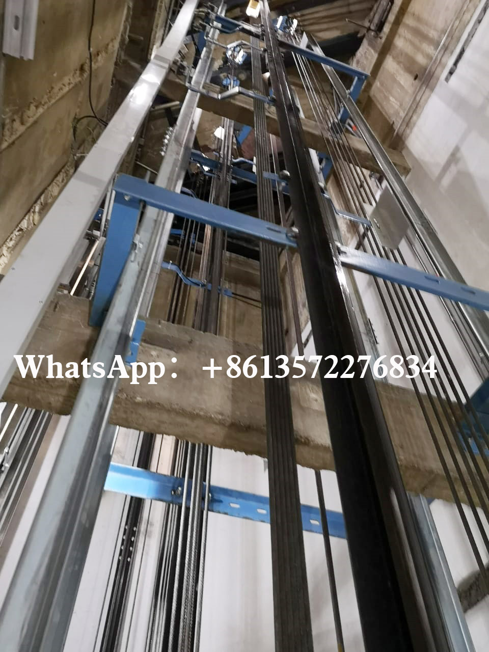
5.1 The installation position of guide rails must meet the requirements of the civil construction layout.
5.2 The distance deviation between the top surface of two rails should be: car rail 0~+2mm; counterweight rail 0~+3mm.
5.3 The installation of rail bracket on the wall of the shaft should be fixed and reliable. The pre-buried parts should meet the requirements of the civil construction layout. Anchor bolts (such as expansion bolts, etc.) should be used on the concrete components of the shaft wall, and their connection strength and ability to withstand vibration should meet the requirements of the elevator product design, and the compression strength of the concrete components should meet the requirements of the civil construction layout.
5.4 The deviation of the working surface (including the side and top surface) of each guideway column from the installation reference line shall not be greater than the following values for every 5m:
5.4.1 0.6mm for the car rail and counterweight (counterweight) rail with safety clamp.
5.4.2 Counterweight (counterweight) rail without safety clamp is 1.0mm.
5.5 There should be no continuous gap at the working surface joint of carriage rail and counterweight (counterweight) rail with safety clamp, and the step at the rail joint should not be larger than 0.05mm. If more than that, it should be repaired and the length of repairing should be larger than 150mm.
5.6 No safety clamp counterweight (counterweight) rail joint gap should not be greater than 1.0mm, rail working surface joint step should not be greater than 0.15mm.
6 Door system
6.1 The deviation of horizontal distance between floor door floor cantilever and car floor cantilever is 0~+3mm, and the maximum distance is strictly prohibited to exceed 35mm.
6.1 Layer door forced closing device must act normally.
6.3 The force to stop the closing of the power-operated horizontal sliding door is strictly prohibited to exceed 150N after 1/3 trip at the beginning of closing.
6.4 The door locking hook must be flexible and the minimum engagement length of the locking element must be 7mm before the electrical safety device for locking is confirmed to operate.
6.5 The clearance between door knife and floor door floor, door lock roller and car floor should not be less than 5mm.
6.6 The level of floor door cantilever shall not be greater than 2/1000, and the cantilever shall be 2~5mm higher than the decoration ground.
6.7 Layer door indicator box, call box and fire switch box shall be installed correctly, and their panels shall be affixed to the wall, and the horizontal and vertical ends shall be correct.
6.8 The clearance between the door fan and the door fan, the door fan and the door sleeve, the door fan and the door lintel, the door fan and the wall of the car at the door, the lower end of the door fan and the ground can, should not be more than 6mm for passenger elevators.
7 Counterweight (balance weight)
7.1 When the counterweight (balance weight) has a counter-rope sheave, the counter-rope sheave should be set with protective devices and rope blocking devices.
7.2 Counterweight (counterweight) block should be fixed reliably.
8 Car
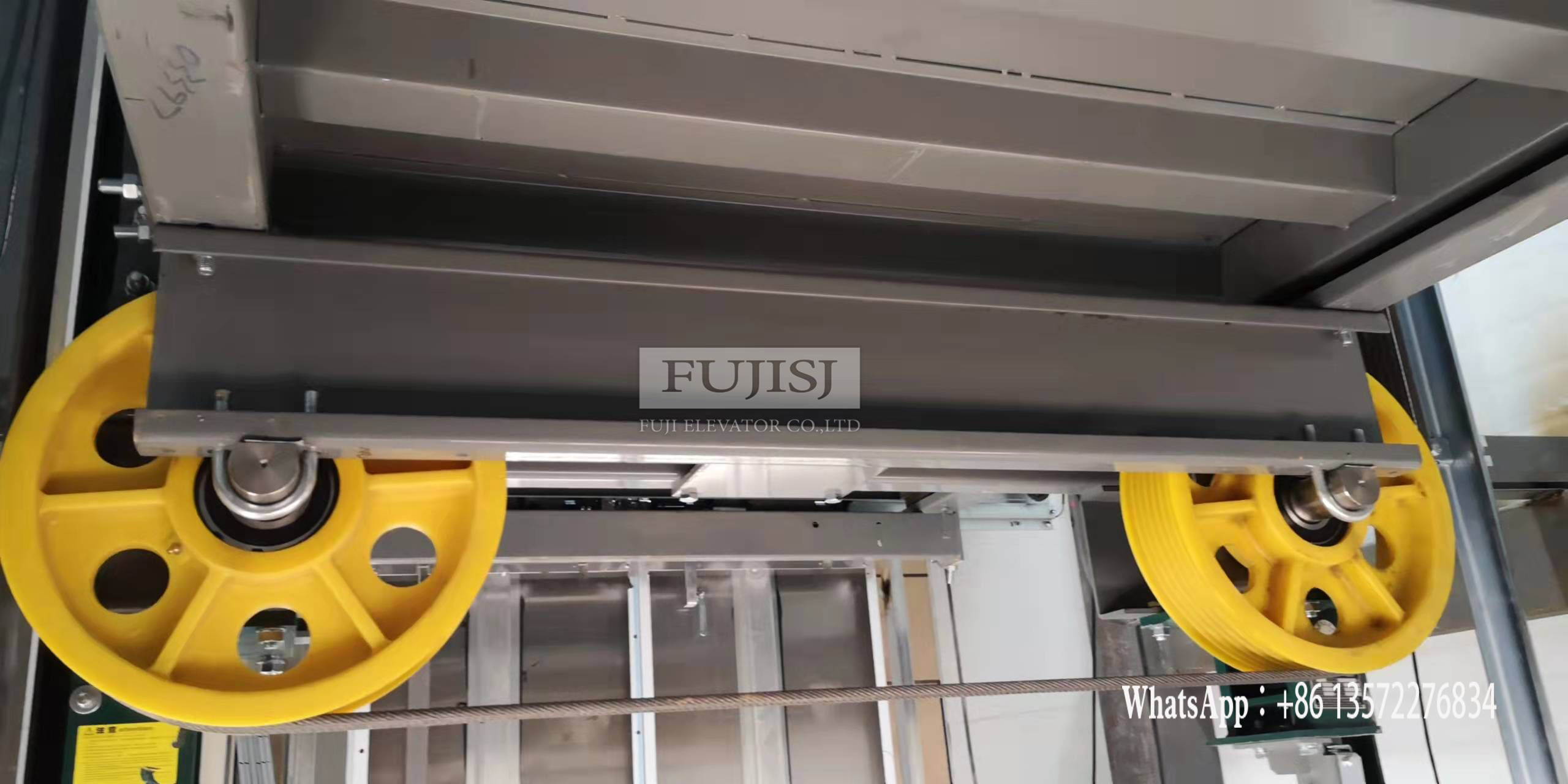
8.1 When the car has anti-rope wheel, the anti-rope wheel should be set with protective device and rope blocking device.
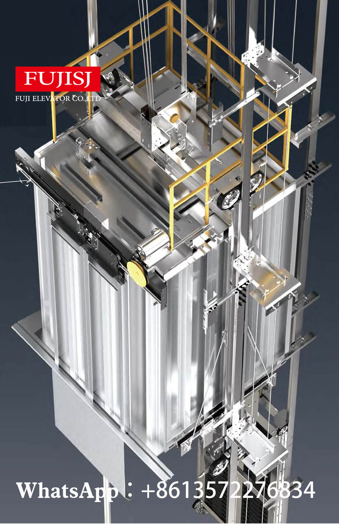
8.2 When the free distance from the outer edge of the car roof to the horizontal direction of the shaft wall is more than 0.3m, the car roof should be equipped with protective fence and warning mark.
9 Safety parts
9.1 The speed limiter action speed setting seal must be intact, and there is no trace of dismantling.
9.2 When the safety clamp is adjustable, the setting seal should be intact and no dismantling trace.
9.3 The relative position of the speed limiter tensioning device and its limit switch should be installed correctly.
9.4 The clearance between safety clamp and rail should meet the requirements of product design.
9.5 When the car is in the level position at both ends, the distance between the buffer plate of the car and counterweight and the top surface of the buffer shall conform to the requirements of the civil construction layout. The deviation between the center of the buffer plate of the car and counterweight and the center of the buffer shall not be more than 20mm.
9.6 The plunger sag of the hydraulic buffer should not be more than 0.5%, and the amount of liquid filling should be correct.
10 Suspension device, accompanying cable, compensation device
10.1 The rope head combination must be safe and reliable, and each rope head combination must be installed to prevent the nut from loosening and falling off the device.
10.2 The wire rope is strictly forbidden to have dead bend.
10.3 When the car is suspended on two wire ropes or chains, and one of the wire ropes or chains occurs abnormal relative extension, the electrical safety switch installed for this purpose should act reliably.
10.4 It is forbidden to have knot and wave twisting phenomenon with the cable.
10.5 Each wire rope tension and the average deviation should not be greater than 5%.
10.6 The installation of the accompanying cable shall conform to the following provisions:
10.6.1 The end of the accompanying cable should be fixed and reliable.
10.6.2 The accompanying cable should avoid interfering with other parts in the shaft during operation. When the car is completely pressed on the buffer, the accompanying cable shall not contact with the floor of the pit.
10.7 The ends of compensation devices such as compensation ropes, chains and cables should be fixed reliably.
10.8 The tensioning wheel of the compensation rope and the electrical safety switch to verify the tensioning of the compensation rope shall act reliably. Tensioning wheel should be installed to protect the device.
11 safety protection acceptance must comply with the following provisions:
11.1 Phase break, wrong phase protection device or function
When any one of the three phases of the power supply of the control cabinet is disconnected or any two phases are misconnected, the phase-break and phase-wrong protection device or function shall keep the elevator from dangerous failure.
Note: When the wrong phase does not affect the normal operation of the elevator, there may be no wrong phase protection device or function.
11.2 Short-circuit and overload protection devices
The power circuit, control circuit and safety circuit must have short-circuit protection devices matching the load; the power circuit must have overload protection devices.
11.3 Speed limiter
The downward sign of the car (counterweight, balance weight) on the speed limiter must match with the actual downward direction of the car (counterweight, balance weight). The rated speed and action speed on the nameplate of the speed limiter must be consistent with the elevator under inspection.
11.4 Safety clamp
The safety clamp must be consistent with its type test certificate.
11.5 Buffer
The buffer must be consistent with its type test certificate.
11.6 Door locking device
Door locking device must be in line with its type test certificate.
11.7 Upper and lower limit switches
The upper and lower limit switches must be safety contacts and must operate normally during the operation test at the end station position. It must act before the car or counterweight (if any) touches the buffer and keep the action state when the buffer is fully compressed.
11.8 The action of the stopping device located in the car roof, machine room (if any), pulley room (if any) and bottom pit must be normal.
12 The following safety switches, must act reliably:
12.1 Speed limiter rope tensioning switch.
12.2 Hydraulic buffer reset switch.
12.3 compensation rope tensioning switch when there is compensation tensioning wheel.
12.4 when the rated speed is greater than 3.5m/s, the compensation rope sheave anti-jump switch; 12.5 the car safety window (the car is not a car).
12.5 Car safety window (if any) switch.
12.6 The switch of safety door, pit door and service flap door (if any).
12.7 safety switches required for detachable emergency operating devices.
12.8 Anti-loosening safety switch when the suspension wire rope (chain) is two.
13 speed limiter safety clamp linkage test must comply with the following provisions:
13.1 speed limiter and safety clamp electrical switch in the linkage test must act reliably, and should make the drive host immediately brake;.
13.2 For instantaneous safety clamp, the car should contain evenly distributed rated load; for progressive safety clamp, the car should contain evenly distributed 125% rated load. When the speed limiter and safety clamp electrical switch is shorted, the car goes down at the speed of maintenance and the speed limiter mechanical action is artificially made, the safety clamp should act reliably and the car must be braked reliably, and the bottom tilt of the car should not be more than 5%.
14 The test of layer door and car door must conform to the following regulations:
14.1 The layer door of each layer must be able to open normally with triangle key:
14.2 When a layer door or car door (any door in multiple doors) is opened abnormally, the elevator is strictly prohibited to start or continue to run.
15 The traction capacity test of traction elevator must conform to the following regulations:
15.1 The car in the upper range of the trip with no load up and the lower range of the trip with 125% of the rated load down, respectively, stopping the floor more than 3 times, the car must reliably stop (no load up working condition should be level). When the car carries 125% of rated load and goes down at normal operation speed, cut off the power supply to the motor and brake, and the elevator must be reliably braked.
15.2 When the counterweight is completely pressed on the buffer and the driving host runs continuously according to the direction of car upward, it is strictly forbidden to lift the car upward with no load.
16 Noise inspection shall conform to the following regulations:
16.1 Machine room noise: for elevators with rated speed less than or equal to 4m/s, it shall not be greater than 80dB(A); for elevators with rated speed greater than 4m/s, it shall not be greater than 85dB(A).
16.2 Noise inside the car during operation of passenger elevators and bed elevators: for elevators with rated speed less than or equal to 4m/s, it shall not be greater than 55dB(A); for elevators with rated speed greater than 4m/s, it shall not be greater than 60dB(A).
16.3 The noise of the opening and closing process of passenger elevators and bed elevators shall not be greater than 65dB(A).
17 Leveling accuracy inspection shall conform to the following regulations:
17.1 AC double-speed elevator with rated speed less than or equal to 0.63m/s shall be within the range of ±15mm.
17.2 AC two-speed elevators with rated speed greater than 0.63m/s and less than or equal to 1.0m/s shall be within the range of ±30mm.
17.3 Elevators of other speed control modes shall be within the range of ±15mm.
17.4 Operating speed inspection shall conform to the following provisions: when the power supply is rated frequency and rated voltage, and the car contains 50% of the rated load, the speed when running down to the middle of the stroke (excluding the acceleration and deceleration section) shall not be greater than 105% of the rated speed, and shall not be less than 92% of the rated speed.
18 Sense inspection shall conform to the following regulations:
18.1 Car door drive layer door open and close operation, door fan and door fan, door fan and door sleeve, door fan and door lintel, door fan and doorway at the car wall, door fan lower end and ground kan should be no scraping phenomenon.
18.2 The respective clearance between the door fan and the door fan, the door fan and the door sleeve, the door fan and the door lintel, the door fan and the car wall at the doorway, and the lower end of the door fan and the ground can be basically the same throughout the length.
18.3 Parts such as machine room (if any), rail bracket, bottom pit, car roof, car interior, car door, layer door and door ground can should be cleaned.
Post time: Jun-07-2022
![富吉-[LOGO]-105](https://www.fujisj.com/uploads/a78ec670.png)


