![富吉-[LOGO]-105](https://www.fujisj.com/uploads/a78ec670.png)

FUJISJ elevator has always been very relevant to the issue of elevator safety, and today we will analyze and discuss the 3 types of emergency rescue methods that can be taken in the event of an elevator failu
1 Using manual release rescue device rescue
1.1 The realization principle of manual release rescue device
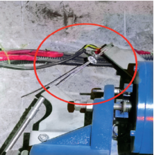
The manual release rescue device is to open the brake through the release wrench to make the car move slowly to the leveling position to achieve the rescue purpose. The operation steps of elevator with machine room are: disconnect the power switch, install the disc driver wheel on the motor shaft (for the removable disc driver wheel, there should also be an electrical safety device, which works at the latest when the installation of the disc driver wheel is completed, one rescuer holds the disc driver wheel, another rescuer pries the brake lever to make the car move slowly, observe the level mark on the wire rope, make the car move to the level area, open the floor door and the car door to rescue the trapped person. For machine-room-less elevator, the manual rescue device is composed of loose gate wrench and wire pulling wire, and the two ends of the wire pulling wire are fixed on the loose gate wrench and brake assembly respectively (see Fig. 1).
For the elevator without machine room which is only equipped with manual rescue device, the operation steps are: under the premise that all the shaft safety doors and layer doors and car doors are closed, lift the loose brake wrench to release the elevator brake, when the car weight and counterweight weight are not equal, the car will move slowly toward the side with lighter weight, observe the observation hole reserved on the shaft or the level indicator (the level indicator should also be lit when the power supply of the elevator is disconnected), and open the layer doors and car doors when the car reaches the level position to rescue the trapped persons. When the car reaches the level position, open the floor door and car door to save the trapped people. If it happens that the weight of the car side and counterweight side are equal at this time, the rescue can be carried out in this way only after the balance is broken with the help of external force [1].
1.2 Problems that should be paid attention to when using manual release rescue device
From the above analysis, it can be seen that the manual rescue device for elevators with machine rooms generally requires two skilled rescuers to cooperate. For elevators without machine rooms, the force required to lift the release wrench is generally larger, and when the weight difference between the car side and the counterweight side is large, the elevator is prone to fast slide if it is not operated properly or is not operated skillfully. The fast ladder not only tests the professional ability of rescuers, but also causes psychological panic to trapped people.
2 Electric loose-brake rescue device rescue
2.1 The principle of electric release rescue device
Electric loose gate rescue is in the utility normal by charging the battery, utility power down through the operation of the device panel button to achieve electric loose gate function. Electric loose gate rescue device generally contains three buttons: start, force and public. The start and public buttons can be pressed at the same time to realize the release of the non-gate area position, and the forced and public buttons can be pressed at the same time to realize the release of the gate area position. The principle of implementation is shown in Figure 2.
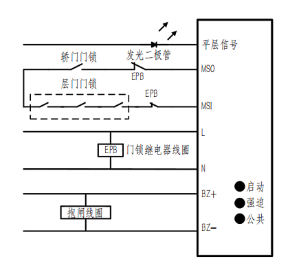
The electric loose-brake rescue device generally outputs two groups of DC power supply: one group is the brake loose-brake voltage, namely BZ+ and BZ- in Fig. 2, with strong excitation of 110V, and the maintenance voltage is generally around 80V; the other group is 24V, which is used for the door area loose-brake sensor power supply and cannot be used for other power supplies. Its rescue process is as follows: when the utility power is cut off, the door lock relay coil EPB loses power, so the two normally closed contacts of EPB close, at this time, if both the floor door and the car door are closed, the car door lock and the floor door lock are closed, and the door lock signal MSO and MSI form a circuit, then the holding brake coil forms a path in 110V DC voltage BZ+~BZ-, the coil gets power and overcomes the spring force to realize the release of the gate. When the car reaches the leveling area, the leveling signal is effective and the light-emitting diode works, at this time the car reaches the leveling position, the rescuer opens the floor door and the car door to rescue the trapped persons.
2.2 Problems that should be paid attention to when using electric loose-gate rescue device
From the above analysis, it can be seen that there are two prerequisites for the correct action of electric loose gate: (1) loss of utility power; (2) layer door and car door are in the closed state. I found in an elevator supervision and inspection, an elevator when disconnected from the power supply, the car door will automatically pop open about 3cm gap, the gap will automatically close after the elevator is powered. Later, it was found that the mechanical locking hook of the car door is equipped with compression spring below, and the spring automatically pops open the car door after power loss to produce gap. From a certain point of view, this design of the manufacturer may be considered for the convenience of rescue and self-rescue of the trapped persons inside the car, but there are also 2 risks: (1) shear risk. If the trapped person inside the car tries to pick open the car door when he finds the gap, if the elevator suddenly gets power, the car door will be closed again, which will produce shear injury to the trapped person inside the car; (2) the car door pops open so that the car door lock is disconnected, then the electric release gate function cannot be realized. Most of the several electric loosening gate devices contacted by the author are external to the door lock circuit, that is to say, the closing of the floor door and the car door is the premise of the electric loosening gate work, which is also out of the safety consideration for the trapped personnel, to prevent the trapped personnel from causing personal injury by misoperation inside the car, which also protects the safety of the trapped personnel to a certain extent [2]. If the weight of the car side and counterweight side is equal, external force is still needed to break the balance to achieve rescue, for example, rescue counterweight can be added on the car roof.
3 Rescue with automatic rescue operation device
3.1 Principle of automatic rescue device
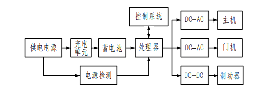
When the utility power is normal, the automatic rescue device is in the state of monitoring the voltage of the power grid; when the elevator loses power or phase, it will automatically put into operation and output power to the elevator, which will run the car to the level state at the rescue speed and drive the car door and floor door to open and release the trapped people. The automatic rescue device is generally set up independently of the elevator and adopts modular design with built-in inverter and rectifier modules and the modules are compatible with each other. Its working principle is as follows: when the utility power is normally supplied, the built-in detection unit of the automatic rescue device sends out a signal that the power supply is normal, and the battery is automatically charged, and its charging circuit has safety protection functions such as over-current, over-voltage and short-circuit. If the car is not in the leveling area, the built-in inverter circuit and rectifier circuit will supply power to the drive host, door machine control system and brake holding circuit respectively, and the car will start to run; when the detection system of the automatic rescue device detects that the car is running to the leveling position, the door machine control system will start to work and the car door and floor door will open at the same time to release the trapped persons. When the detection system of the automatic rescue device detects that the car is running to the flat floor position, the door machine control system starts to work and the car door and floor door open simultaneously to release the trapped persons. The working principle is shown in Figure 3.
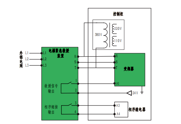
The following is an example of a brand of automatic rescue device to illustrate its specific implementation. Its electrical schematic is shown in Figure 4. When the external power grid is lost, the internal processor will detect the main power out of phase (some manufacturers are also through the auxiliary normally closed contacts of the sealed star contactor to achieve detection), after waiting for a period of time (the requirements of the inspection rules are at least 3s from the external power grid outage) its built-in battery unit (generally 4 groups of 12V power) will be converted into 380V AC output to the elevator control cabinet through the inverter circuit unit. The isolation transformer inside the elevator control cabinet will then reduce 380V to 220V and 110V respectively to supply power to the door motor circuit and the holding circuit. If the brake circuit is DC powered, the rectifier unit should be added (if the brake is equipped with an independent brake power module and has a built-in rectifier module, the rectifier unit is not needed). After the above process is completed, the control circuit of the elevator will take over the operation of the elevator according to the signal of the automatic rescue device, and move the elevator to the leveling position slowly, at which time the door electric circuit will control the car door to open and thus drive the floor door to open, thus completing the whole rescue process. When the external power supply is restored, the phase sequence relay will be activated normally, and the automatic rescue device will not work at this time to avoid the voltage of the inverter backing up to the power grid side and the conflict between the normal power grid supply and the output voltage of the rescue device. It can also be seen from Figure 4 that the 48V battery pack not only provides input voltage for the inverter, but also provides 24V DC power for the internal processor.
3.2 Inspection points of automatic rescue device and issues to be noted
According to TSG T7001-2009 “Elevator Supervision, Inspection and Periodic Inspection Rules – Traction and Forced Drive Elevators” (including No. 1, 2, 3 revised list), the inspection requirements for automatic rescue devices are: (1) a nameplate indicating the name of the manufacturer, product model, product number, main technical parameters, the nameplate of the installed automatic rescue operation device and the device (2) automatically put into rescue operation after waiting for at least 3s for the power failure of the external power grid, the elevator automatically levels and opens the door; (3) when the elevator is in maintenance operation, emergency electric operation, electrical safety device action or the main switch is disconnected, it shall not be put into rescue operation; (4) there is a non-automatic reset switch, when the switch is in the closed state, the device cannot start rescue operation [3].
The above (1) and (4) are relatively simple, and (2) power failure waiting time can generally be set and adjusted. The most important is Article (3), when the main switch is disconnected automatic rescue device shall not be put into operation, that is, the automatic rescue device is an emergency operation under the external power grid outage conditions. I also found in the inspection process before some elevators when the main switch is disconnected, automatic rescue devices will automatically make the elevator run to the level position and open the door, which obviously does not meet the requirements of the inspection rules. In the inspection should be found to break the main switch of the upper circuit breaker, but often encountered in the inspection process is that the upper circuit breaker will generally control other electrical equipment or even break the power supply of the entire building, and the upper circuit breaker will generally be far from the main switch or emergency operation screen, which brings inconvenience to the actual inspection. For this situation, it is recommended to add an auxiliary test switch between the upper level circuit breaker and the main switch to avoid directly cutting off the upper level circuit breaker [4].
From the elevator manufacturing standards automatic rescue device does not belong to the safety components, July 1, 2022 implementation of TSG T7007-2022 “elevator type test rules” also did not include it in the scope of the type test. The author believes that the current requirements of the automatic rescue device can refer to the relevant requirements of the elevator bypass, such as the state of the floor door and car door during the operation of the automatic rescue device, the sound and light alarm in the car to comply with the regulations. The above analysis also shows that the state of the floor door and car door is crucial to the safety of the rescue process, so further regulations should be made. The soon to be implemented GB/T 7588.1-2020 “Safety Code for Elevator Manufacturing and Installation Part 1: Passenger Elevator and Freight Elevator” puts forward higher requirements for the emergency operation device, namely: within 1h after the occurrence of a fault, the power supply should be able to make the car with any load move to the nearby floor station and the running speed of the elevator should not be greater than 0.3m/s.
4 Conclusion
Emergency rescue is a rescue operation under extreme working conditions, and the manufacturing units, maintenance units and users of the above three rescue devices should each do their part to ensure safety, i.e.: the manufacturing units should combine the elevator manufacturing standards and elevator type test rules to be implemented to improve the reliability of product performance and quality; the maintenance units should strengthen the appearance and functional inspection of the rescue devices to ensure that the loose brake wrench The main responsibility should be taken by the user unit to strengthen the supervision of the maintenance unit and do a good job of emergency rescue drills.
As an elevator inspector, we should follow the requirements of the inspection rules to check each article, and at the same time, we should strengthen the study of the working principle of the elevator and the electrical schematic diagram, so as to combine theory and practice, find problems in the inspection process, solve problems and ensure the safe operation of the elevator.
[1] Zhou Xi. Exploration on the inspection of elevator automatic rescue operation device [J]. China Elevator,2021,32(21):39-40,59.
[2] Yang World. The working principle of common elevator automatic rescue operation device and its inspection[J]. China Elevator,2020,31(14):40-42.
[3] TSG T7001-2009, Elevator supervision and periodic inspection rules – traction and forced drive elevators [S].
[4] Wang Chao. Discussion on the principle and inspection points of common machine-roomless elevator emergency rescue devices [J]. China special equipment safety, 2020, 36(7):61-65, 70.
Reprinted: This article was published in China Elevator Magazine, No. 14, 2022
Author: Shen Shulin, Sheng Yiqian, Dai Yang, Cai Dawei / Suqian Branch, Jiangsu Institute of Special Equipment Safety Supervision and Inspection
Post time: Oct-17-2022

